CONTENT
Design of the New Electricity Generation System and Its Operation…p.1
Introduction ……….………………………………………………………………………… p.1
The Structure of the System……………………………………………………………… p.2
Operation of the System…………………………………………………………………… p.3
The Maintenance of the System………………………………………………………… p.4
The General Sheme of the Systeme…………………………………………………… p.5
The Piece of the Systeme………………………………………………………………… p.6
The Pieces of the Systeme……………………………………………………………… p.7
Design of the New Electricity Generation System and Its Operation
Introduction
A member of HEGEM (Lifelong Education and Development Center) Association, Associate Professor Dr. Kemal DURUHAN in the field of education philosophy at Inonu University has developed a system pledging a significant difference in power generation. This technological design which is believed to cure the global warming thanks to the environment-friendly energy it generates in a renewable and sustainable way.
The system will be able to operate in any kind of still water, either natural or artificial, (Sea, Lake, pond or pool) entirely under human control throughout the year (7X24) based on renewal and sustainable power generation principle.
The system pledges increasing the global power generation hundreds times in a cost- and time-affective way and the resulting clean and environment-friendly power will terminate the need for all fossil fuels currently used in power generation. The generated electricity will be so plenty that it will allow the implementation of electricity-driven cars and roads, it will facilitate illumination, industrial manufacture, and heating. Moreover, this system can be used in marine transportation.
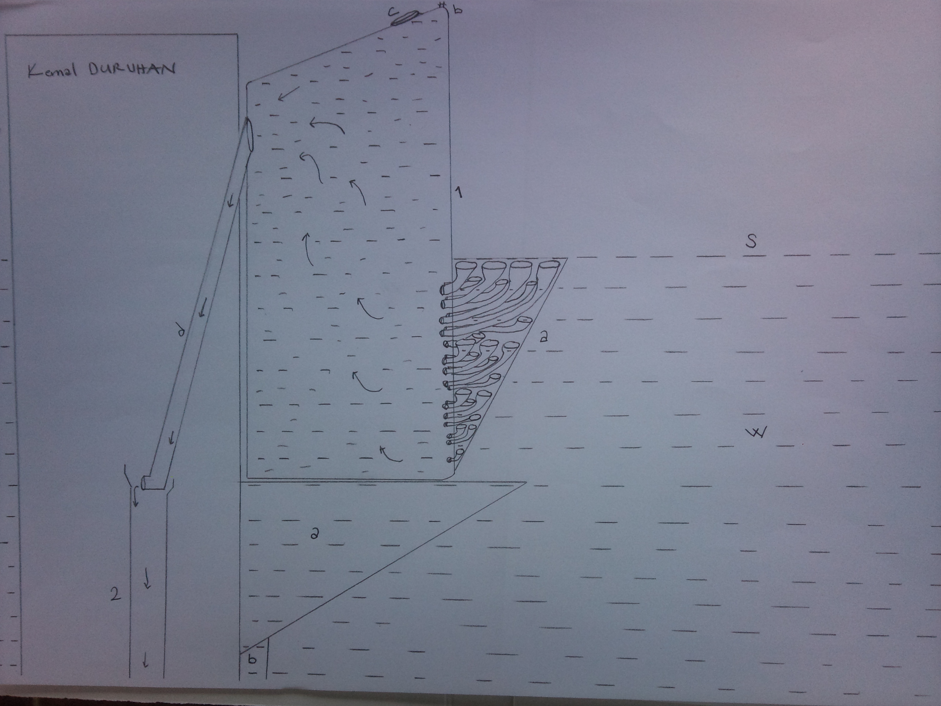
This system is a hydroelectricity power plant, which is placed onto water floor in non-flowing water (e.g. sea, lake, pond, pool), surrounded by walls, with its center open from bottom to top and in contact with atmosphere, which has a transitive water reservoir with its top above the water surface level adjacent to the outer wall of the plant and some part under water and higher than non-flowing water mass level. The system is based on generating electricity by transmitting the flowing water through penstock into flow pipe
Its difference from other hydroelectricity power plants is that it is not placed over the river flow regime but into the non-flowing water. These hydroelectricity power plants can be designed in different places and various sizes as single and multiple structures with one or more turbine(s) depending on the water’s volume.
The Structure of the System
B: Floor
W: Non-flowing water Mass
S: Surface of the non-flowing water mass
1: Transitive Water Reservoir
1a: Passage Pipes
1b: Air release, Water pumping mechanism
1c: Transient water reservoir lid
1d: Penstock
2: Flow Pipe
2a: Electric Turbine
2b: Lidded End of Flow Pipe
2c: Lidded Intake of Water Catchment Pipe
3: Plant Walls
3a-b: Transitive Water Reservoir Foundations
3c: The Pipe transmitting the electricity generated and delivered to the city
4: Water Catchment Pool
4a: Outlet of Water Catchment Pipe
4b: Motor-driven Water Discharge Mechanism
Operation of the System
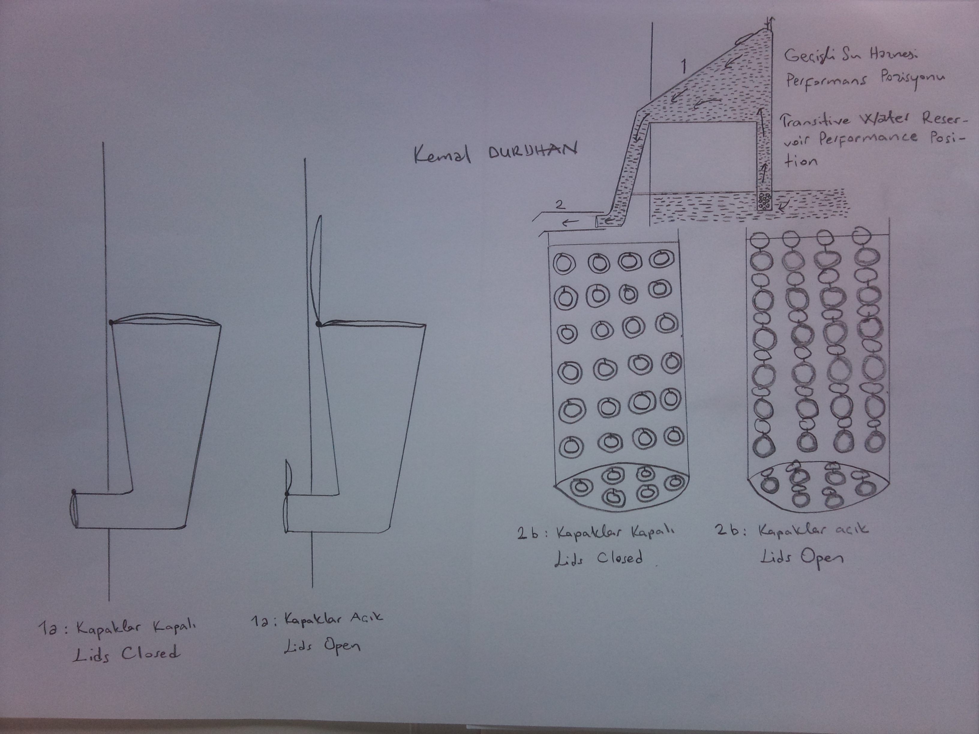
The system is made ready for operation by closing the lid of the penstock and the lids of the passage pipes in and out of the water reservoirs, allowing the reservoir to fill with water completely (including the entire penstock) through the top lid. The upper part of the penstock is above the non-flowing water mass level and its lower part is below the non-flowing water mass level. As the lid of the penstock opens, thanks to the force of gravity, the water flows downward with a momentum. With the resulting pulling force, the lids of the passage pipes open (the lids of the parts in the transitive water reservoir opens naturally with the pulling force caused by the water flowing down the penstock. The lids of the parts out of the water reservoir and in the non-flowing water mass) and the non-flowing water mass is transmitted to the water reservoir. The water flowing through the penstock is sent to the flow pipe in contact with atmosphere and in open space. Next, the flowing water is discharged into non-flowing water mass through the one-way lids of the flow pipes outside the plant, which open outward.
To improve the operation of the system to a great extent, the following principles should be noted:
The total diameter of the ends of the passage pipes in the water reservoir cannot be bigger than the diameter of the end of the penstock. The diameters of the penstock and flow pipe are nearly the same. Transitive water reservoir should be placed slightly inclining to the left in order to allow the water mass in the transitive water reservoir to apply high pressure to the water in penstock.
In order to improve the operation performance of the system, the length and connections of the penstock and flow pipe must be adjusted by the engineers.
The Maintenance of the System
After the mouth of the penstock is closed with a lid, the lid of water catchment pipe that is in the end of flow pipe in plant will automatically open and the remaining water in the flow pipe gathers in the water catchment pool. Since the water in the flow pipe discharged, non-flowing water mass will rush towards flow pipe and causes the lids to close. This enables the maintenance of the system.
The water that was gathered in the water catchment pool is discharged into the non-flowing water mass with the help of motor that work with electrical energy obtained when the system worked again.
The air filled at the top part of the transitive water reservoir in time due to the air resolved in water is released and replaced with water using an air release and water pump mechanism.
The General Scheme of the System
The Piece of the System
The Pieces of the Systeme

Resim 1: Genel Sistem Şeması
Resim 2: Düzenek Şeması 1
Resim 3: Düzenek Şeması 2
Elektrik Enerjisi Üretimi İçin Geliştirilen Sistem Tasarımının Tanıtılması ve Sistem Düzeneğinin Çalışması
Doç. Dr. Kemal DURUHAN
Giriş
Sistem durgun su (deniz, göl, gölet, havuz) içerisinde zemine konuşlanmış olarak yapılan kenarları duvarlarla çevrili, ortası zeminden yukarısına kadar açık ve atmosferle temasta, üstü durgun su seviyesinin yukarısında kalan, dış duvarına bitişik, bir kısmı su içerisinde ve durgun su kütlesinden yüksek bir yapıda geçişli su haznesi olan ve cebri boru ile akış halinde olan suyun akım borusuna aktarılarak elektrik enerjisi üretildiği bir hidroelektrik santralidir. Diğer hidroelektrik santrallerinden temel farkı akarsu rejimi üzerine değil; durgun su içerisine konuşlandırılmış olmasıdır. Bu Hidroelektrik Santralleri durgun su hacminin kapasitesine bağlı olarak değişik yerlerde ve değişik büyüklüklerde tekil ve çoklu bir şekilde bir veya birden fazla türbinli olarak tasarlanabilir.
Sistem Düzeneği
B: Zemin
W: Durgun Su Kütlesi
S: Durgun Su Kütlesinin Yüzeyi
1: Geçişli Su Haznesi
1a: Geçiş Boruları
1b: Hava Boşaltma, Su Pompalama Düzeneği
1c: Geçişli Su Haznesi Kapağı
1d: Cebri Boru
2: Akım Borusu
2a: Elektrik Türbini
2b: Akım Borusunun Kapaklı Ucu
2c: Su Toplama Borusu Kapaklı Giriş Ağzı
3: Santral Bina Duvarları
3a-b: Geçişli Su Haznesi Dayanakları
3c: Üretilen ve şehre verilen elektrik enerjisi İletim Borusu
4: Su Toplama Havuzu
4a: Su Toplama Borusu Çıkış Ağzı
4b: Motorlu Su Tahliye Düzeneği
Sistem Düzeneğinin Çalışması
Sistem, cebri boru ağzının sürülerek bir kapak ile kapatılıp, geçiş borularının su haznesi içerisindeki ve dışarısındaki kısımlarının ağızlarının küçük bir tıklanma ile kapatılarak su haznesine, üstündeki kapağından içerisinin (cebri borunun tamamı dâhil) tamamen su ile doldurulmasıyla çalışmaya hazır hale getirilir. Üst seviyesi durgun su kütlesinin seviyesinden yukarı ve alt seviyesi durgun su kütlesinin seviyesinden aşağı olan cebri borunun ağzının kapağının açılmasıyla yer çekimi etkisindeki suyun ivmelenerek aşağıya doğru akmasıyla oluşan çekimle durgun su kütlesi, geçiş borularının kapaklarının açılması yoluyla (Geçişli su haznesi içinde kalan kısımların kapakları, cebri borudan aşağı doğru akan suyun oluşturduğu çekimle insan müdahalesine gerek kalmadan kendiliğinden açılır. Su haznesi dışında ve durgun su kütlesi içinde kalan kısımların kapakları insan müdahalesiyle bir mekanizma marifetiyle açılabilir) su haznesine aktarılır. Cebri borudan akan su atmosfer basıncıyla temasta ve açık ortamda akım borusuna akıtılarak elektrik üretimi gerçekleştirilir. Sonrasında akışına devam eden su, akım borusunun santral binasının dışında kalan, borunun dışarısına doğru açılan ve içerisine doğru kapanan kapaklı kısımlarından durgun su kütlesi içerisine tahliye edilir.
Sistem işleyişinin yüksek düzeyde iyileştirilmesi için aşağıda sayılan hususlara dikkat edilmesinde fayda vardır;
Geçiş borularının su haznesi içerisinde kalan ağız kısımlarının toplam genişliği cebri boru ağzının genişliğinden daha az olamaz. Cebri boru ile akım borusu daire çapları aşağı yukarı birbirine eşittir. Geçişli su haznesi içerisindeki su kütlesinin cebri boru içindeki su kütlesine yüksek basınç uygulayabilmesi için geçişli su haznesinin sola doğru hafifçe eğik durumda konuşlandırılması gerekir.
Sistem Düzeneğinin Bakımı
Cebri borunun ağzının bir kapak ile kapatılmasıyla, akım borusunun santral binası içerisinde kalan uç kısmındaki su toplama borusunun kapağı otomatik bir şekilde açılarak, akım borusunda kalan su, su toplama havuzuna toplanır. Akım borusu içindeki suyun boşalması nedeniyle durgun su kütlesi, akım borusuna doğru hücum ederek kapakların kapanmasına neden olur. Böylece sistem bakımı yapılabilir hale gelir.
Su toplama havuzuna toplanan su, sistem tekrar çalıştırıldığında elde edilen elektrik enerjisiyle çalışan motorla, durgun su kütlesi içerisine tahliye edilir.
Hava boşaltma ve su pompalama düzeneği marifetiyle, geçişli su haznesi tepe kısmına zaman içerisinde su içerisindeki eriyik hava nedeniyle dolan hava boşaltılıp, yerine su pompalanır.
Introduction to the design of electricity generation system and its operation
Associate Professor Dr. Kemal DURUHAN
Introduction
This system is a hydroelectricity power plant, which is placed onto water floor in non-flowing water (e.g. sea, lake, pond, pool), surrounded by walls, with its center open from bottom to top and in contact with atmosphere, which has a transitive water reservoir with its top above the water surface level adjacent to the outer wall of the plant and some part under water and higher than non-flowing water mass level. The system is based on generating electricity by transmitting the flowing water through penstock into flow pipe
Its difference from other hydroelectricity power plants is that it is not placed over the river flow regime but into the non-flowing water. These hydroelectricity power plants can be designed in different places and various sizes as single and multiple structures with one or more turbine(s) depending on the water’s volume.
The Structure of System
B: Floor
W: Non-flowing water Mass
S: Surface of the non-flowing water mass
1: Transitive Water Reservoir
1a: Passage Pipes
1b: Air release, Water pumping mechanism
1c: Transient water reservoir lid
1d: Penstock
2: Flow Pipe
2a: Electric Turbine
2b: Lidded End of Flow Pipe
2c: Lidded Intake of Water Catchment Pipe
3: Plant Walls
3a-b: Transitive Water Reservoir Foundations
3c: The Pipe transmitting the electricity generated and delivered to the city
4: Water Catchment Pool
4a: Outlet of Water Catchment Pipe
4b: Motor-driven Water Discharge Mechanism
Operation of the system
The system is made ready for operation by closing the lid of the penstock and the lids of the passage pipes in and out of the water reservoirs, allowing the reservoir to fill with water completely (including the entire penstock) through the top lid. The upper part of the penstock is above the non-flowing water mass level and its lower part is below the non-flowing water mass level. As the lid of the penstock opens, thanks to the force of gravity, the water flows downward with a momentum. With the resulting pulling force, the lids of the passage pipes open (the lids of the parts in the transitive water reservoir opens naturally with the pulling force caused by the water flowing down the penstock. The lids of the parts out of the water reservoir and in the non-flowing water mass) and the non-flowing water mass is transmitted to the water reservoir. The water flowing through the penstock is sent to the flow pipe in contact with atmosphere and in open space. Next, the flowing water is discharged into non-flowing water mass through the one-way lids of the flow pipes outside the plant, which open outward.
To improve the operation of the system to a great extent, the following principles should be noted:
The total diameter of the ends of the passage pipes in the water reservoir cannot be bigger than the diameter of the end of the penstock. The diameters of the penstock and flow pipe are nearly the same. Transitive water reservoir should be placed slightly inclining to the left in order to allow the water mass in the transitive water reservoir to apply high pressure to the water in penstock.
In order to improve the operation performance of the system, the length and connections of the penstock and flow pipe must be adjusted by the engineers.
The maintenance of the system
After the mouth of the penstock is closed with a lid, the lid of water catchment pipe that is in the end of flow pipe in plant will automatically open and the remaining water in the flow pipe gathers in the water catchment pool. Since the water in the flow pipe discharged, non-flowing water mass will rush towards flow pipe and causes the lids to close. This enables the maintenance of the system.
The water that was gathered in the water catchment pool is discharged into the non-flowing water mass with the help of motor that work with electrical energy obtained when the system worked again.
The air filled at the top part of the transitive water reservoir in time due to the air resolved in water is released and replaced with water using an air release and water pump mechanism.